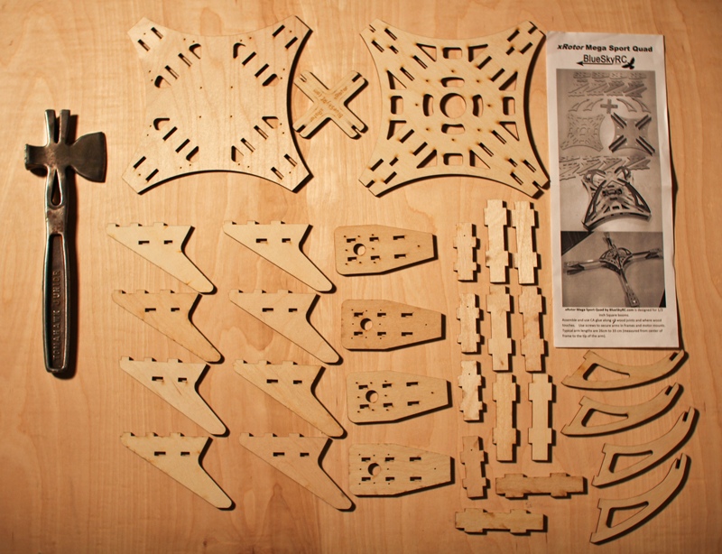
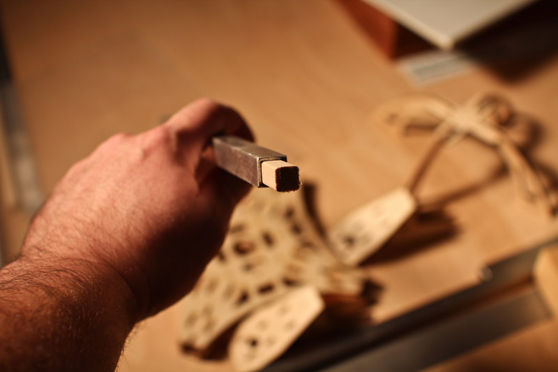
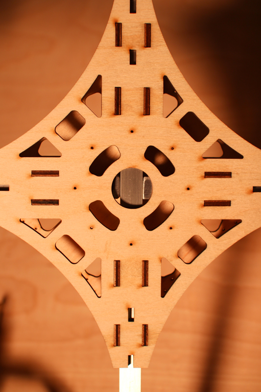
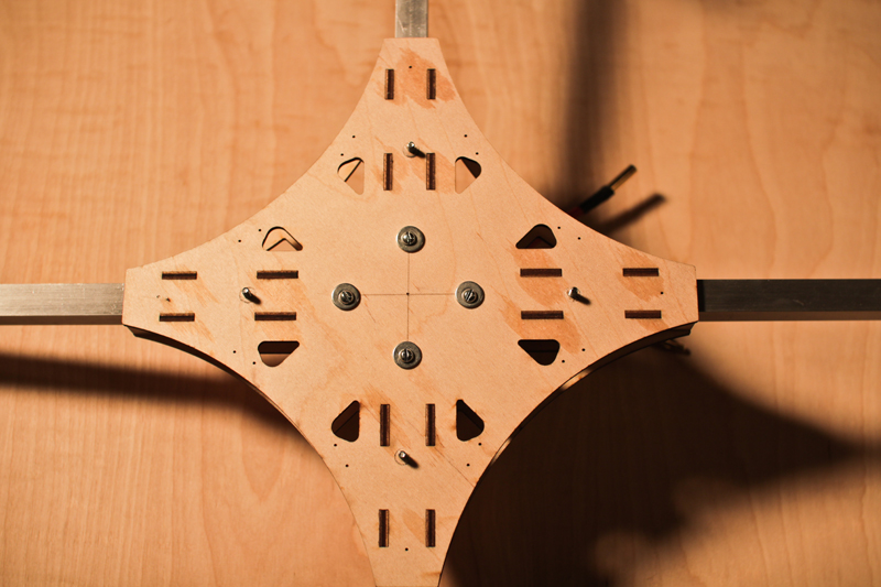
The first step in frame assembly is to put all the parts together and check that they all fit together snug. I used the tomahawk mini hammer you see in the photos to firmly tap the parts together and get rid of any gaps or spaced between the wood. The cutting of this little kit frame is very precise. Nice laser cutting!
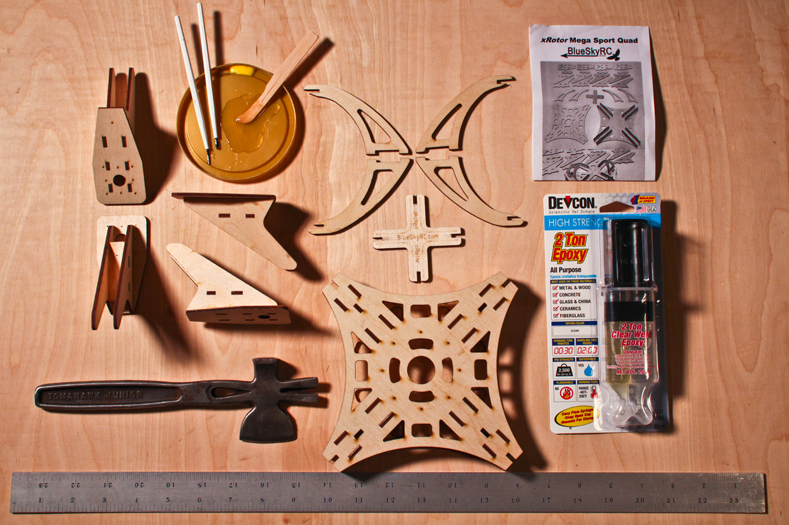
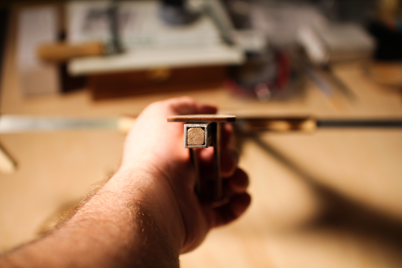
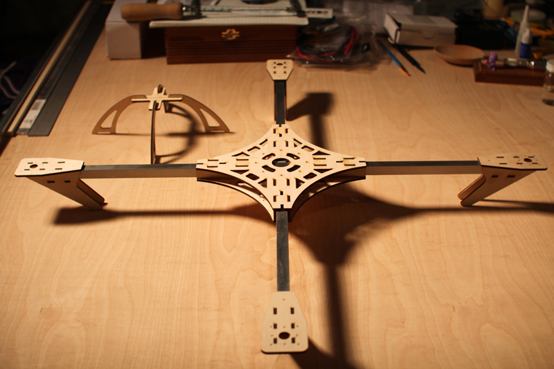
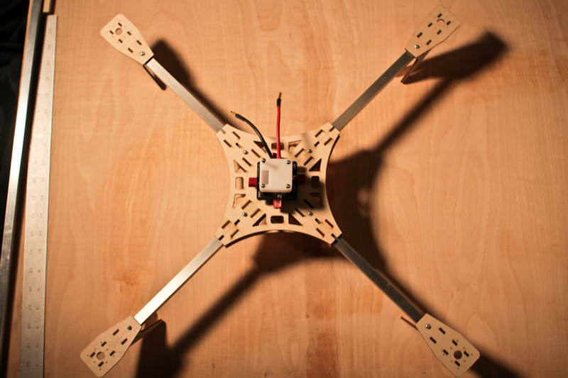
The second step is to test fit the 1/2″ aluminum booms prior to gluing the parts together. This is done to be sure they fit snugly through the holes they are meant to slide through. I found mine to fit very precisely in the space provided. Finally, its time glue together the wood parts using CA glue, epoxy, or wood glue. I used epoxy because I suspect it will give me the strongest bond. I selected an epoxy with a 30 minute working time and a 2 hour set time. I used small paint brushes to apply epoxy along all the assembly joints where wood touches. I also put weights on top of the main body in order to insure that the component would be completely flat after the epoxy dried (meaning no warping). I elected to wait on adding the protective roll cage on top of the frame in order to allow myself more space during the construction process. Here is a shot of the assembled frame and its components:
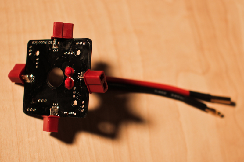
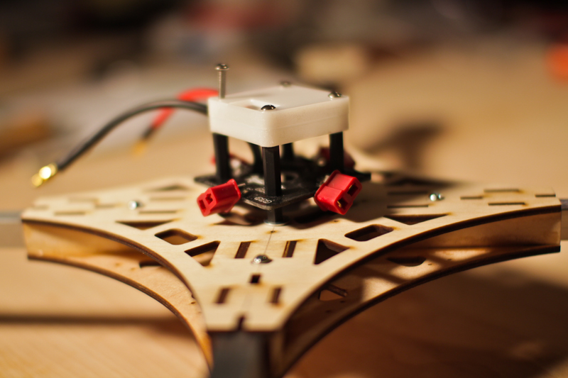
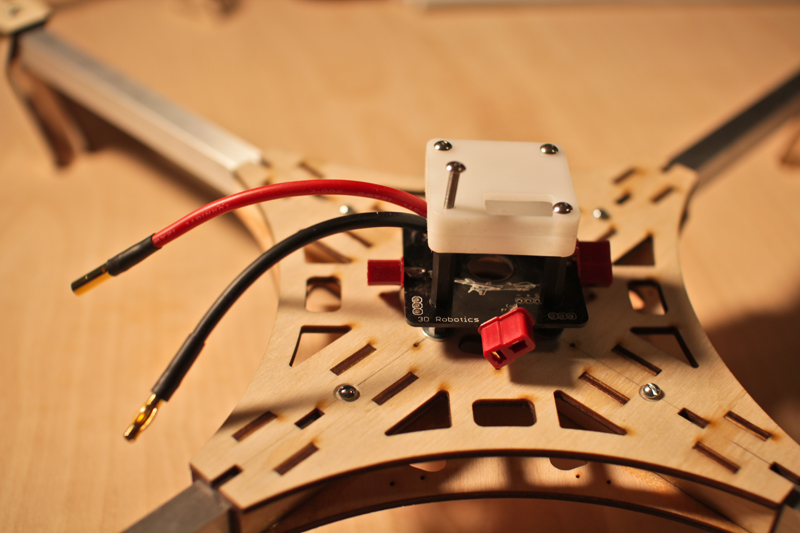
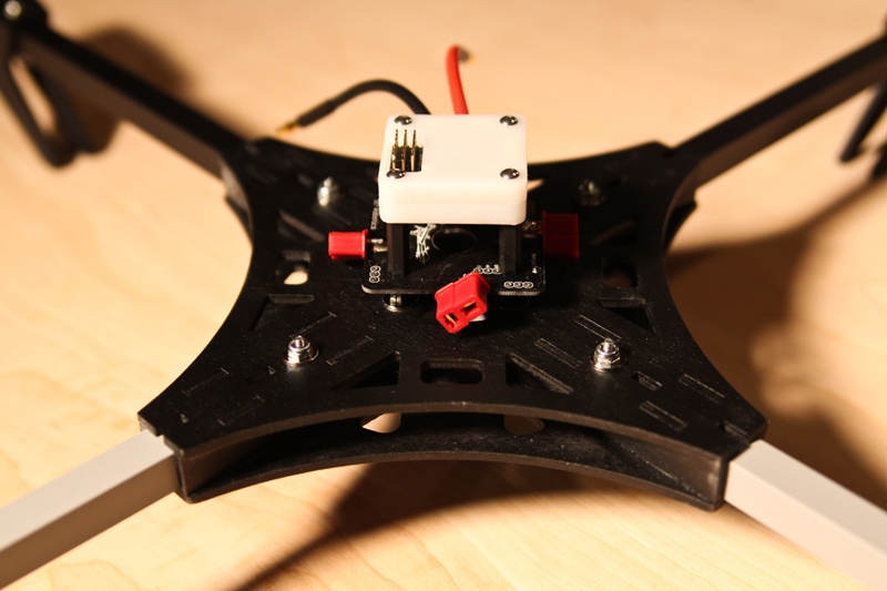
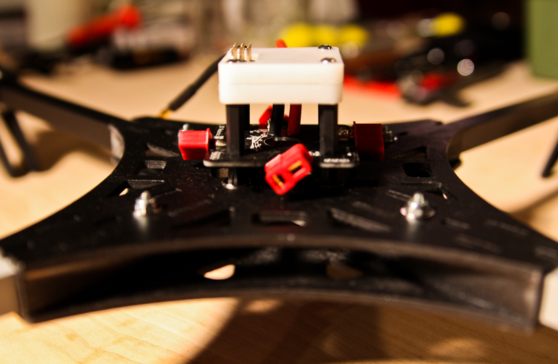
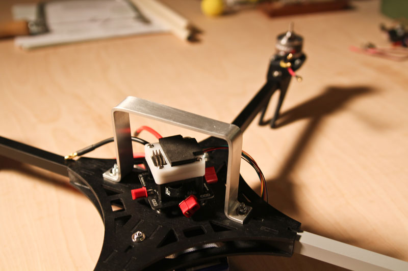
After reading some crash horror stories, I chose not to mount the CC board naked. I found a little case made by Frankenquad that nicely protects the electronics, as you can see in the photos. The CC board fits perfectly inside this case.
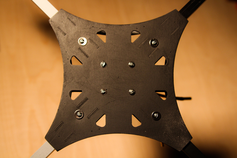
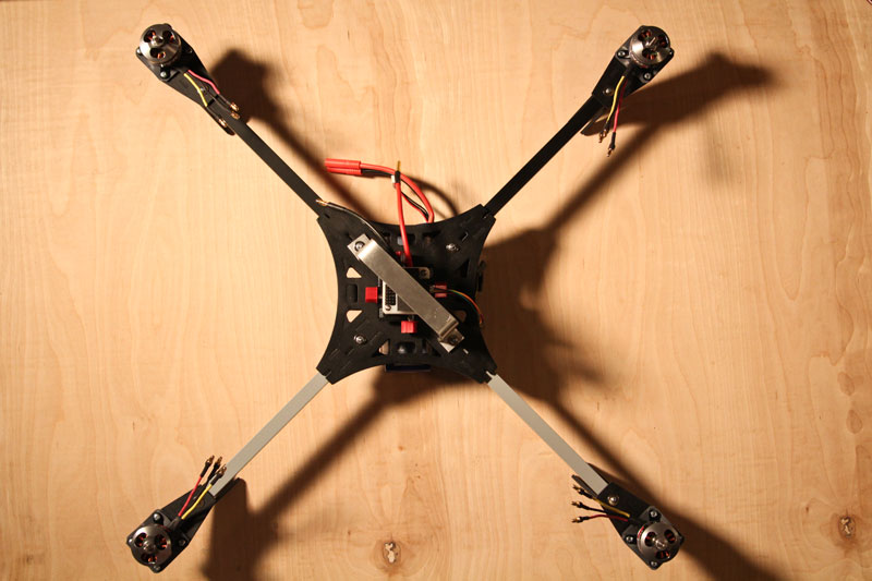
The mounting screws for the boards pass through the frame and the aluminum arms as you can see in the photo of the bottom of the copter.
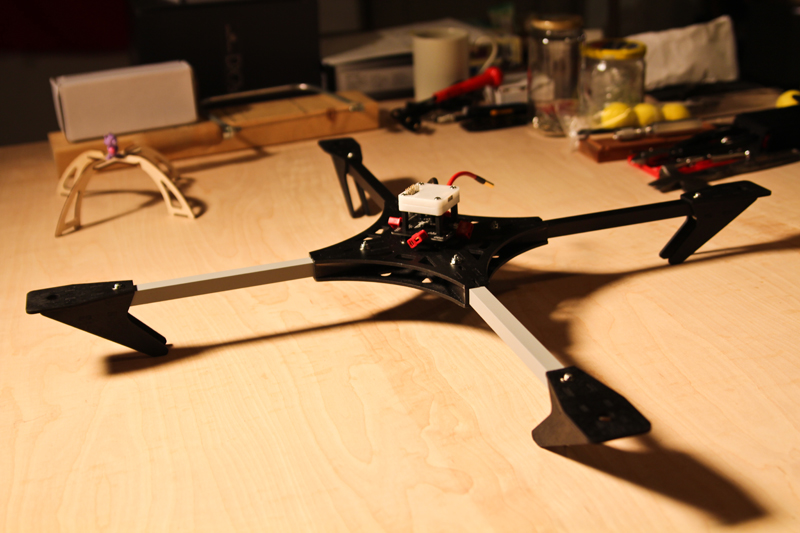
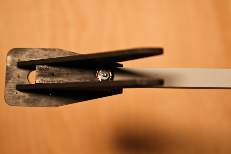
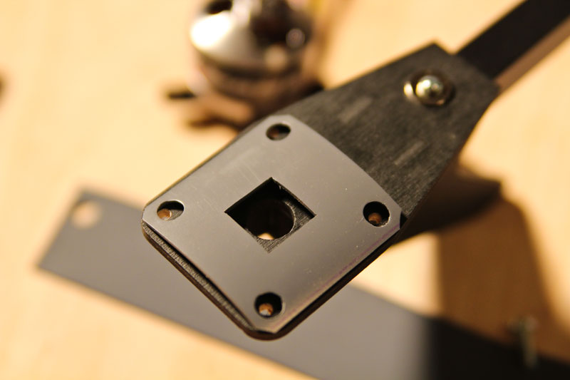
Everything will be mounted to the arms via 1″ machine screws using washers, lock washers, and thread lock (yes, this may be overkill!). As for the motor mounts, I mounted them so that the aluminum arm is flush with the edge of the mounting hole on the outside of the wooden motor mount (see photo). They are currently attached with one bolt, however I may add a set screw on the bottom or a second bolt at some point. I am considering using the inboard motor mount screw to pass through the motor, wooden motor mount, and the aluminum arm in order to save a little weight and material.
The next thing I’ll do is paint! Looking at a flat black/grey color scheme.
The arms are attached to the frame with 8 bolts total. 4 of those 8 bolts are used to hold the power distribution board and Copter Control board in place as well. The motor mounts are held in place by one bolt apiece for the time being and they seem pretty sturdy. Everything fits tight and the frame seems to be pretty stiff. I went with flat black and grey on the paint.
Here it is:
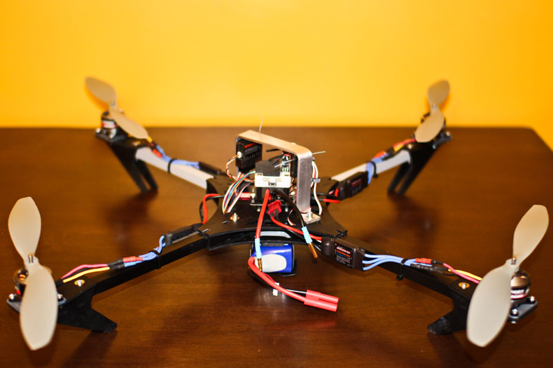
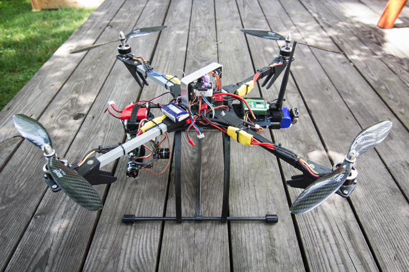
1. Mounted motors – I used 2 sheets of some tub lining rubber I had lying around to mount the motors on. This served a 2-fold purpose – to dampen vibrations and to make some space for the motor shafts since they were rubbing on the wooden motor mounts a little bit. It definitely worked for the second purpose! As for vibration dampening, I don’t think it can hurt.
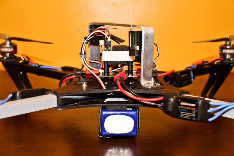
2. I scrapped the wooden roll cage provided by Blue Sky R/C in this Mega Quad kit because it interfered with my access to the bolts holding the boards in place. I bent myself a nice piece of aluminum bar. I found it to be simple, and really sturdy. It’s also a nice carrying handle. It is bolted all the way through the arms (with their basswood centers) and the wooden frame. As you’ll see in my first crash test video, this little aluminum guard was worth its weight in gold. It saved all my electronics on each of my 4 crashes.
3. Next, I mounted the battery with two velcro straps and a piece of foam taped along the bottom of the frame to protect the top of the battery from being damaged by machine screw heads. During my crash testing, I came to find that I should probably add some velcro on the actual battery.
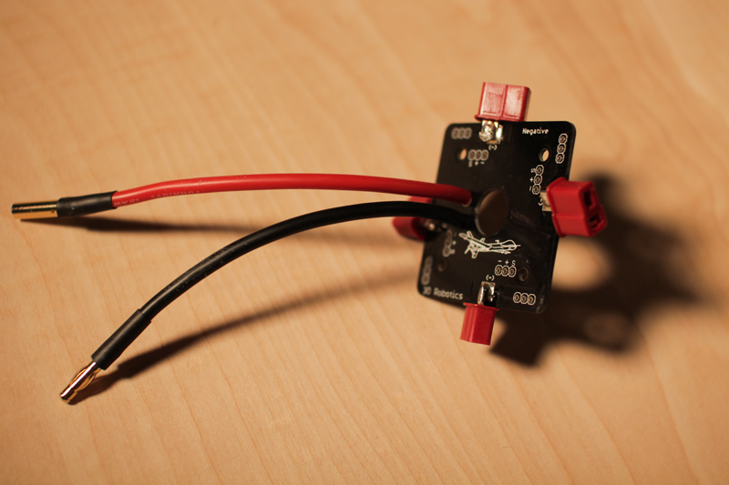
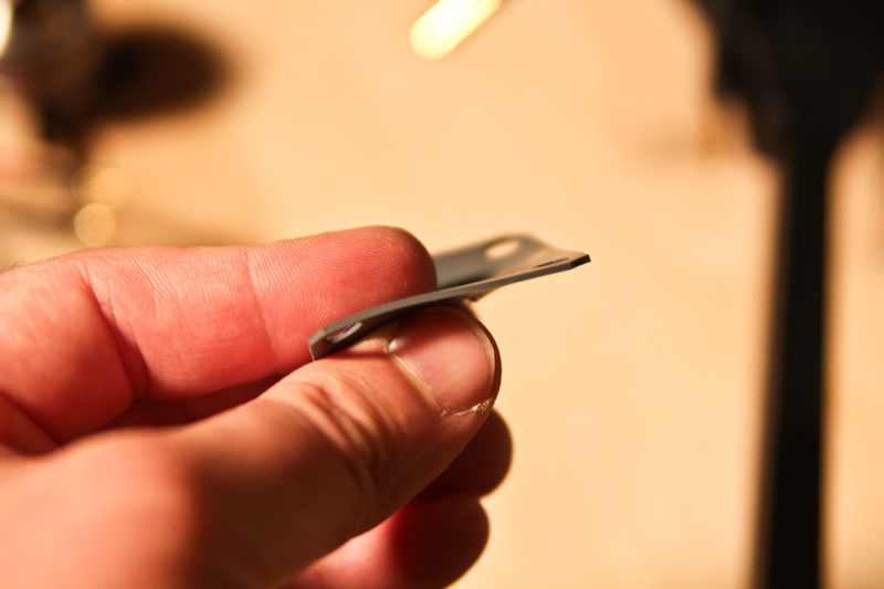
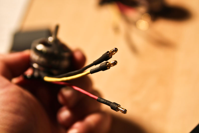
4. Changed the 4mm banana connectors on the ESCs to male Deans connectors so that they would plug into my power board.
5. Wired everything up (Receiver, satellite, ESC’s, Motors, Battery, CC Board) and arranged things as neatly as I possibly could at my current skill level!
6. Proceeded to read and follow Matt’s 101 Guide and watched the Copter Control Basics videos…then proceeded to run into some problems I addressed in the forums, followed by some minor crash testing.

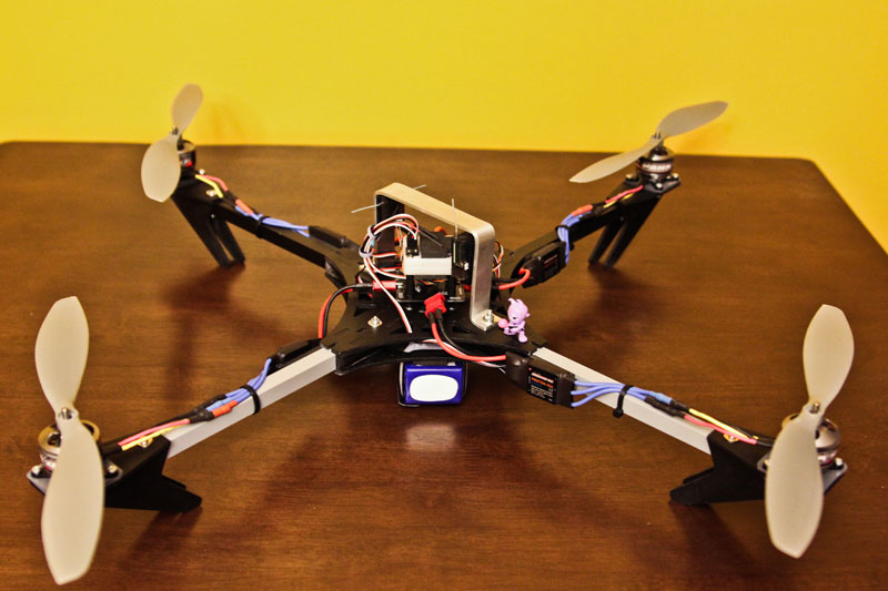
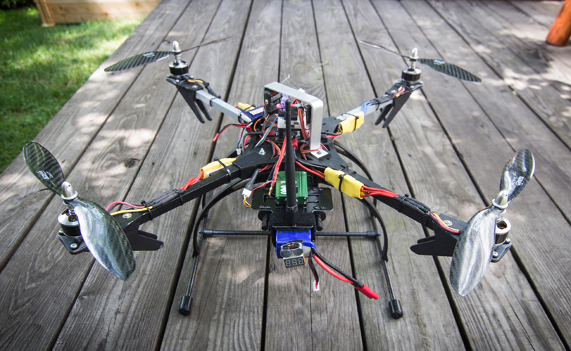
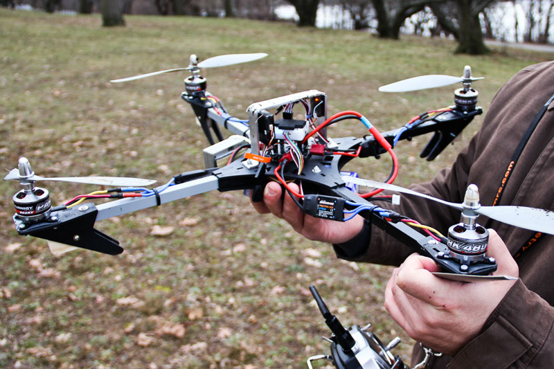
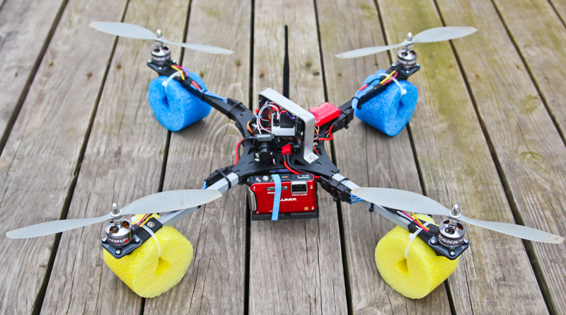
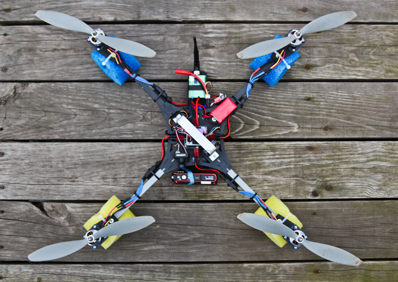
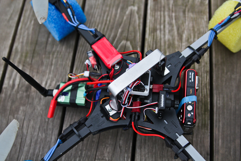
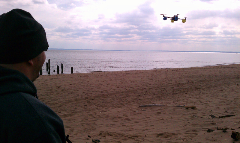
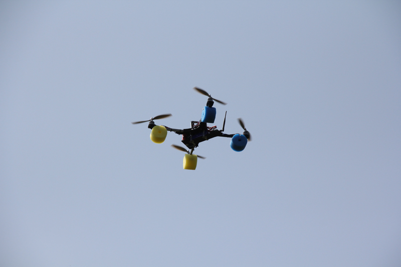
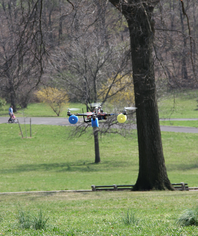
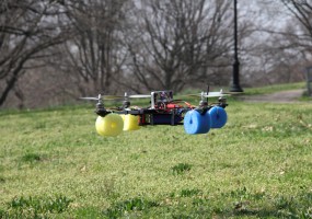
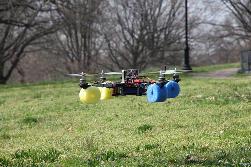
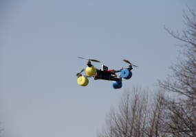
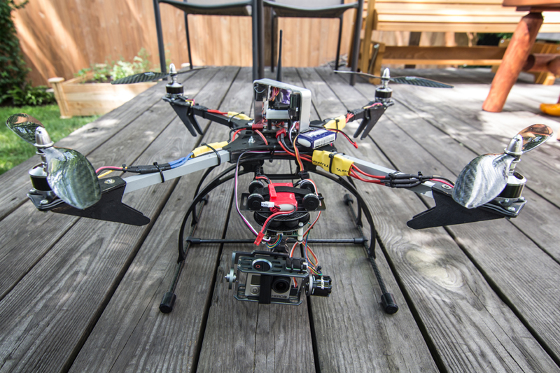
Below are some photos of this build. Note how it has evolved over time. One of the benefits to building a MultiRotor from scratch with basic materials is the ease with which you can repair, add, or modify the flying machine to suit your requirements. This one went from an easy to land(crash!), colorful pool noodle machine – to a brushless gimbal slinging aerial photo/video platform. It is also set up for FPV flying. Building and tinkering with a MultiRotor takes time, and there is a learning curve. The upside to putting in the time is that you’ll be able to fix and troubleshoot your own problems when you run into them. All those companies advertising problem free, turnkey solutions are giving novice users the false hope that this technology is at the point where it is ready to be used maintenance and problem free (yes DJI, you) . That just isn’t the case right now. It may be in the future, but I personally know that even a $10,000 “turnkey” aerial photography solution is anything but. There will be issues, and they’ll be really annoying if you know nothing about them! So if you do choose to get into this, learn a little before you spend your hard earned cash.
-
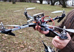
- My first quadcopter after a crash that broke two props and one ego
-
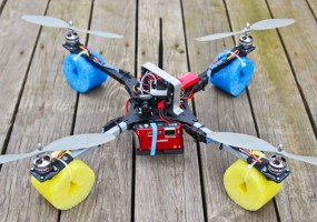
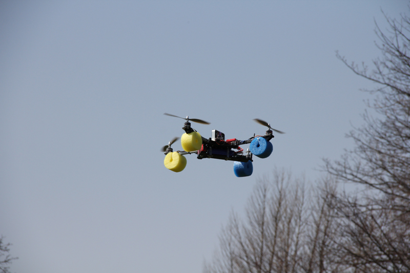
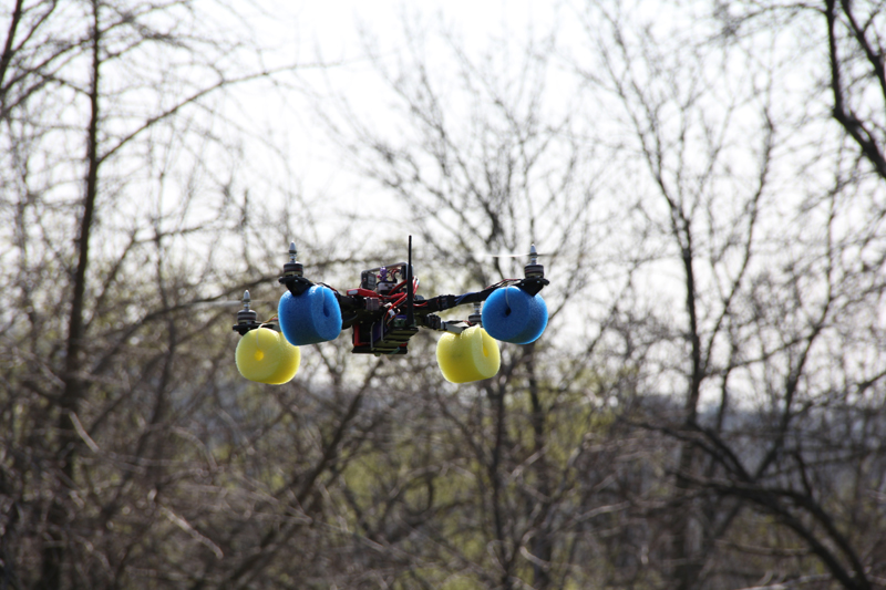
- My first quadcopter build modified with fpv gear and pool noodle landing gear
-

- My first quadcopter build modified with fpv gear and pool noodle landing gear
-
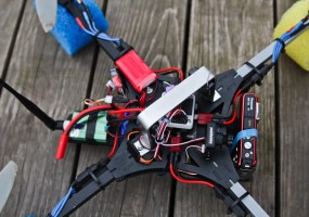
- My first quadcopter build modified with fpv gear and pool noodle landing gear
-
- My first quadcopter build modified with fpv gear and pool noodle landing gear
-
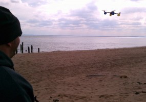
- My first quadcopter build modified with fpv gear and pool noodle landing gear
-

- My first quadcopter build modified with fpv gear and pool noodle landing gear
-
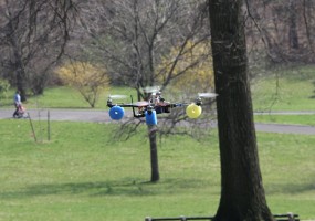
- My first quadcopter build modified with fpv gear and pool noodle landing gear
-
- My first quadcopter build modified with fpv gear and pool noodle landing gear
-
- My first quadcopter build modified with fpv gear and pool noodle landing gear
-
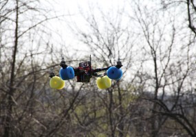
- My first quadcopter build modified with fpv gear and pool noodle landing gear
-
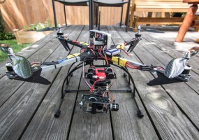
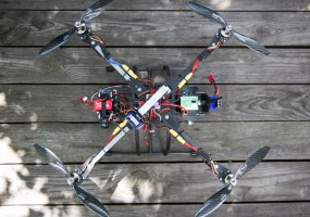
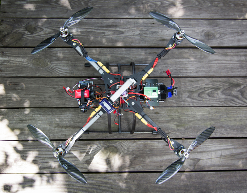
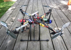
- My first quadcopter build modified with tall landing skids and a brushless gimbal
-
- My first quadcopter build modified with tall landing skids and a brushless gimbal
-
- My first quadcopter build modified with tall landing skids and a brushless gimbal
-
- My first quadcopter build modified with tall landing skids and a brushless gimbal